| |


Next: Transport Control Module
Up: Control Board
Previous: Fader Module
Contents
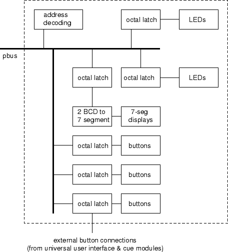
The output assignment module shall contain eighteen momentary buttons,
two digits of 7-segment LED displays, sixteen LEDs, and the necessary Pbus
interface circuitry. Additionally, it shall provide a means
of interfacing the additional buttons of the cue and universal interface
sections of the control board. Figure
13 shows the functional diagram of
the output assign board.
Figure 13:
Control board, output assignment module diagram.
 |
Steve Richardson
2000-07-06
|
Table of Contents
![[PDF]](/~prefect/images/pdficonsmall.gif) [Whole document in PDF 1.9MB]
[Whole document in PDF 1.9MB]
[more photos and information]
|